MAVLink

NOTE
Enabling MAVLink forces the use of Hybrid or 16ch/2 switch mode. Wide switch mode is not supported. Enabling MAVLink forces a telemetry ratio of 1:2
Overview
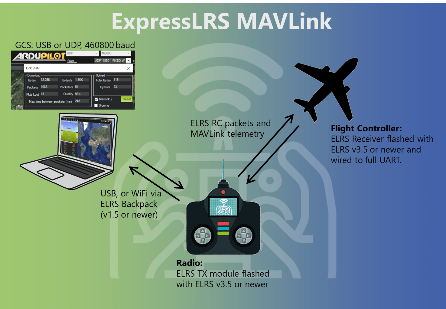
ExpressLRS provides full bi-directional MAVLink support, enabling both native MAVLink telemetry downlink and RC control uplink over a single radio link. This integration allows you to use ExpressLRS hardware as a complete replacement for traditional telemetry radios while maintaining RC control functionality.
Key Benefits
- Single radio link and UART for both RC control and telemetry (no separate telemetry radio needed), and only one UART is needed on the flight controller for both RC and telemetry
- Better range than traditional telemetry radios thanks to LoRa modes
- Stubborn sender ELRS uses its stubborn telemetry sender system for MAVLink messages - this system retries packets that weren't delivered, keeping MAVLink link quality high over longer distances and/or with interference. This ensures reliable delivery of MAVLink messages, even in situations where there is significant packet loss
- Full parameter editing and mission planning support
- Compatible with all major GCS software (Mission Planner, QGroundControl, etc.)
Hardware Requirements
To start using MAVLink, you just need one ESP based ELRS transmitter, and one ESP based ELRS receiver. The majority of recent ELRS hardware is ESP based, and will be compatible with MAVLink. An easy way to check is, if the RX/TX have WiFi, then it is ESP based. STM32 based hardware cannot support running MAVLink mode.
900MHz Performance Warning
It is STRONGLY suggested that you avoid using MAVLink mode with single-band 900MHz hardware. If you are planning to use 915/868MHz ELRS hardware, MAVLink will be SIGNIFICANTLY slower than with 2.4GHz or dual-band 900MHz. This is due to the much lower data rates available on legacy 900MHz hardware.
Expected performance on legacy (single-band) 900MHz:
- At the 200Hz packet rate with 1:2 telemetry ratio: ~400 bps (bits per second)
- At 100Hz Full packet rate with 1:2 telemetry ratio: ~400 bps
- At any of the lower rates: Unusable data speeds, don't even bother.
- Parameter downloading at 200Hz takes 2+ minutes
For comparison, with dual-band hardware at K1000Hz (which still uses the 900mhz band) the data rate is ~4000 bps, and parameter download takes ~4 seconds.
Recommendation: Use 2.4GHz or dual-band (LR1121) hardware for MAVLink whenever possible. If you must use the older 900MHz hardware, be prepared for very slow data transfers.
NOTE: Internal TX modules
If you are using an internal TX module (e.g. a TX16S with internal ELRS), you will be required to use the TX Backpack to connect to you GCS via WiFi (USB cable between the TX and the PC is not an option for internal modules). See WiFi Connectivity below.
Flashing ELRS for MAVLink
Ensure both your transmitter module, the embedded TX-Backpack (if using WiFi forwarding), and your receiver are up to date with the latest release versions:
- For the main ELRS firmware, follow the Firmware Update Guide for detailed instructions.
- For the TX-Backpack, follow the Transmitter Backpack Firmware Guide for detailed instructions.
The minimum versions to use this feature are: - Transmitter / receiver firmware: 3.5.0 - TX Backpack firmware: 1.5.0
Configuring ELRS TX & RX for MAVLink
-
Turn on both the RX and TX, and ensure they are bound, connected, and communicating. In the ELRS Lua script look for a C in the top-right corner of the screen which indicates that the TX module and receiver are connected and communicating.
-
Set the protocol on the RX UART to MAVLink.
- For ELRS v3, with the TX and RX still connected, in the ELRS Lua script, select
Other Devices, select your receiver, and set theserial protocoltoMAVLink. - For ELRS v4, this step can be skipped. RX protocol is now configured automatically when changing the TX mode to MAVLink.
- For ELRS v3, with the TX and RX still connected, in the ELRS Lua script, select
-
Turn off your receiver, link mode cannot be changed when connected. In the main menu select the
Link Modeoption. Change it fromNormaltoMAVLink. This configures the TX module to send / receive MAVLink. -
Configure your usual power, packet rate, etc. The telemetry ratio will be preset to 1:2 (and cannot be changed while in MAVLink mode).
-
Power on your receiver and verify it is connected and communicating with the transmitter. As above look for the C in the top-right.
-
Wire the RX to a free UART on your flight controller that is suitable for TLM + RC. A DMA-capable UART is recommended.
Flight Controller Setup
For the below steps, when a UART connection is mentioned, it will be written as SERIALx. Replace x with the UART number you are using.
- Configure
SERIALx_PROTOCOL=2,SERIALx_BAUD=460, andRSSI_TYPE=5 - Configure all
SRx_parameters to be1, except forSRx_ADSB,SRx_PARAMS,SRx_RAW_CTRLthat should stay0(otherwise yaapu will see a few sensors only and GCS might not be able to connect) - Save parameters and reboot the flight controller
For the below steps, when a UART connection is mentioned, it will be written as SER_TELx. Replace x with the UART number you are using.
- Configure SER_TELx_BAUD to
460800 8N1 - Configure MAVLink with MAV_0_CONFIG to
TELEM2 - Configure MAVLink sending rate with MAV_0_RATE to
9600 B/s - Save parameters and reboot the flight controller
Released versions of INAV (from version 8 onwards) can use MAVLink for flight monitoring. However, given that INAV is primarily an MSP flight controller, full functionality and configuration via MAVLink should not be expected.
For the below steps, when a UART connection is mentioned, it will be written as UARTx. Replace x with the UART number you are using.
- In the Ports tab, set the UARTx
Telemetry ProtocoltoMAVLink, and the baud rate to460800. Make sureRX Serialis disabled. - In the Receiver tab, set the Receiver type to
SERIALand theSerial Receiver ProvidertoMAVLink. Leave inverted & half-duplexdisabled. - In the CLI, enter
set mavlink_radio_type=ELRSto get the correct RSSI and LQ values on INAV's OSD. - Save and reboot the flight controller.
Betaflight 2025.12.0-beta and later includes improved MAVLink support with software flow control (via the RADIO_STATUS message). You MUST use Betaflight 2025.12.0-beta or later for MAVLink to function with ELRS.
For the below steps, when a UART connection is mentioned, it will be written as UARTx. Replace x with the UART number you are using.
- In the Ports tab, on the UARTx row, make sure
RX Serialis enabled, set theTelemetry OutputtoMAVLink, and the baud rate to460800. - In the Receiver tab, set the Receiver type to
Serial (via UART)and theSerial Receiver ProvidertoMAVLINK. - Save and reboot the flight controller.
Handset Setup
Once your flight controller and ExpressLRS hardware are configured for MAVLink, you should have RC control of your craft from your handset. Setup your RC and switch channels as normal in the EdgeTX model screens.
Handset Telemetry
ELRS converts the MAVLink telemetry into standard CRSF format which is understood by EdgeTX. On the Telemetry page in EdgeTX, click "Discover new" to see GPS, battery stats, flight mode, etc.
Yaapu Lua script does not work with ELRS MAVLink in v3.x.x but is supported in v4.x.x.
Connecting to the Ground Control Station
You are now ready to connect your Ground Control Station (GCS) software to the TX module. ExpressLRS supports two connection methods: Serial (USB) and WiFi (UDP). Choose the method that best suits your setup.
Connection Methods Overview
| Method | Use Case | Pros | Cons |
|---|---|---|---|
| Serial (USB) | Direct wired connection | Reliable and easy setup, no WiFi needed, works anywhere | Requires USB cable between the TX and PC which limits mobility, Does not work with internal modules (e.g. internal TX16S module or similar) |
| WiFi (UDP) | Wireless connection via TX Backpack | Cable-free, mobile GCS operation, works with internal modules | Requires TX Backpack, more setup required, limited by WiFi range |
Serial (USB) Connection
Serial connection provides a direct, reliable link between your GCS and the TX module via USB cable. This is the recommended method for first-time setup, assuming your TX module supports it (not suitable for internal modules).
Mission Planner Setup (Serial)
-
Connect Hardware:
- Connect your TX module to your computer via USB cable
- Ensure the TX module is powered on and bound to your receiver
- Power on your aircraft so that the TX and RX are linked
-
Configure Connection:
- Launch Mission Planner
- In the top-right connection panel, click the dropdown menu next to "Connect"
- Select the COM port corresponding to your TX module
-
Set Baud Rate:
- Select
460800from the baud rate dropdown - This is the fixed baud rate for ExpressLRS MAVLink
- Select
-
Connect:
- Click the Connect button
- Mission Planner should connect and begin receiving telemetry
- The HUD should display flight data, GPS position, battery voltage, etc.
QGroundControl Setup (Serial)
If you are on Windows, QGroundControl requires a recent daily build to support the DTR USB settings needed for ExpressLRS hardware.
-
Download and Install:
- Download the latest daily build from QGroundControl Daily Builds
- Install and launch QGroundControl
-
Disable Auto-Connect:
- Click the Q icon (Application Settings) in the top-left corner
- Select Comm Links from the sidebar
- Turn off all the auto-connect toggles at the top of the page
- This prevents QGC from connecting with the wrong USB settings
-
Create New Connection:
- Click the Add button (bottom of the screen) to create a new comm link
- Give it a descriptive name like "ExpressLRS TX Module"
-
Configure Serial Link:
- Set Type to
Serial - Connect your TX module via USB
- Select your COM/Serial port from the dropdown:
- Windows: COM port number (e.g., COM3, COM5)
- Linux:
/dev/ttyUSB0or/dev/ttyACM0 - macOS:
/dev/cu.usbserial-*
- Set Baud Rate to
460800
- Set Type to
-
Configure DTR (Critical Step):
- Click Advanced Settings to expand additional options
- Configure based on your operating system:
- Windows: ✅ Check the
Force DTR Lowcheckbox - Linux: ⬜ Leave the
Force DTR Lowcheckbox unchecked - macOS: ⬜ Leave the
Force DTR Lowcheckbox unchecked
- Windows: ✅ Check the
Windows Users: DTR MUST Be Low
On Windows, you must enable "Force DTR Low" or the connection will fail and your TX module will reboot / lockup. This is due to how Windows handles serial port control signals with ESP32 hardware. This setting is a recent addition to QGC which is why the daily builds are suggested.
-
Save and Connect:
- Click OK to save the comm link
- Select your new comm link from the dropdown
- Click Connect
- QGroundControl should connect and display vehicle telemetry
WiFi Connectivity
For TX modules that have an onboard Backpack, the MAVLink data can be sent / received via WiFi to a PC or tablet etc. that is running the GCS software. This provides for a cable-free solution on your handset, as it removes the need for a USB cable between the TX and the GCS device.
A Note on WiFi Network Modes
The Backpack supports two WiFi modes:
-
Access Point (AP) Mode: Creates its own WiFi network with SSID
ExpressLRS TX Backpack XXXXXX- Best for field use where no existing WiFi network is available
- Limited range (typically 5-10m depending on environment)
- Direct WiFi connection between GCS device and TX Backpack
-
Home WiFi (STA) Mode: Connects to your home WiFi network
- Best for bench and indoor use
- Uses you existing home WiFi infrastructure for extended range
- GCS and Backpack must be on the same network
Setup WiFi Forwarding for MAVLink
-
Ensure the TX Backpack is running version
1.5.0or later -
In the ELRS Lua script, select
Backpack, scroll to theTelemetryoption, and change the value toWiFiAttention!
DO NOT manually put the TX Backpack into WiFi mode via
WiFi Connectivity -> Enable Backpack WiFi. It's not in the steps above for a reason.When you set
TelemetrytoWiFimode in the ELRS Lua script, the Backpack automatically:- Starts WiFi mode
- Configures the WiFi service for MAVLink forwarding
- Sets up the UDP ports correctly
Manual WiFi enable puts the Backpack in firmware update mode, not MAVLink mode!
-
If you are NOT using Home WiFi on the Backpack, a new WiFi access point will be available to connect to:
- SSID format:
ExpressLRS TX Backpack XXXXXX(whereXXXXXXis part of your module's UID) - WiFi password:
expresslrs - The Backpack will use IP
10.0.0.1in AP mode
Alternatively, if you ARE using Home WiFi on the Backpack, the Backpack will automatically start WiFi and connect to your router.
- SSID format:
-
Connect your PC or tablet to the Backpack's WiFi network (or the same home network)
-
Power on the craft so that the TX and RX have an active link
-
Make sure no firewall is blocking UDP traffic (e.g. Linux: disable
ufw, Android: select "use network as is") -
Configure your GCS software:
Mission Planner Setup (UDP)
-
Connect to Backpack WiFi:
- Connect your computer to the TX Backpack's WiFi network
- SSID:
ExpressLRS TX Backpack XXXXXX(where XXXXXX is part of your UID) - Password:
expresslrs - Or connect to your home network if using STA mode
-
Configure UDP Connection:
- Launch Mission Planner
- In the top-right connection panel, click the dropdown and select UDP
- Click the Connect button
- A dialog box will appear asking for the port number
-
Set Port:
- Enter
14550(the default MAVLink UDP port) - Click OK
- Enter
QGroundControl Setup (UDP)
-
Connect to Backpack WiFi:
- Connect your device to the TX Backpack's WiFi network
- SSID:
ExpressLRS TX Backpack XXXXXX - Password:
expresslrs - Or connect to your home network if using STA mode
-
Enable Auto-Connect:
- Open QGroundControl
- Click the Q icon (Application Settings)
- Select Comm Links
- Turn on the auto-connect toggle for UDP (it should be on by default unless you have disabled it)
- QGroundControl should automatically connect and receive telemetry as soon as your Backpack starts sending it
Best Practices and Tips
Choosing Packet Rates
For MAVLink, higher packet rates provide better telemetry data speeds.
Suggested settings:
- 2.4GHz: Best speeds will be achieved with F1000 packet rate. We recommended that you use F1000 or 333Hz Full for the initial parameter download and any mission uploads. When you are ready to fly, switch to 333Hz Full (or 250Hz etc.) for longer range at slower data rates.
- Dual Band: Best speeds will be achieved with K1000 packet rate. We recommended that you use K1000 for the initial parameter download and any mission uploads. When you are ready to fly, switch to 200Hz Full (if you want a 900MHz band) for longer range at slower data rates. Alternatively, switch to 333Hz Full (if you want a 2.4GHz band).
- Single band 900MHz: Legacy 900MHz packet rates are NOT recommended. If you insist on using these rates / hardware, we suggest you use the maximum 200Hz packet rate.
Advanced Features
MAVLink System IDs (Optional)
MAVLink uses System IDs (SysID) to identify different devices on the network. ExpressLRS allows you to configure these IDs to match your setup:
- Source SysID: The System ID that the ExpressLRS receiver uses when acting as a GCS (Ground Control Station). Default is
255, which is the standard GCS ID. -
Target SysID: The System ID of your flight controller/vehicle. Default is
1, which is the standard vehicle ID.When to Change System IDs
In most cases, the default values (Source: 255, Target: 1) work perfectly. You may need to change these if:
- You have multiple vehicles on the same MAVLink network
- Your flight controller uses a non-standard System ID
- You're integrating with other MAVLink devices (companion computers, gimbals, etc.)
To configure System IDs:
- Set the receiver to MAVLink mode (as described above)
- Power on the TX and RX so that they are linked (solid LED on the RX)
- Open the ELRS Lua script, navigate to
Other Devicesand select your receiver - Set
Target SysIDto match your vehicle's System ID (typically1) - Set
Source SysIDto your preferred GCS System ID (typically255) - Save and reboot
The receiver will now use these IDs for all MAVLink communication, ensuring proper message routing in complex MAVLink networks.
Standalone Telemetry Radio Mode
ExpressLRS TX modules can be used as standalone telemetry radios, similar to traditional SiK radios, without requiring a connection to a handset. This mode is useful for:
- Fixed-wing long range flights where you only need telemetry (separate RC control)
- Bench testing and configuration
- Autonomous missions where RC control is not needed
How to Use Standalone Mode
-
Before using the TX module standalone, you will need to setup the packet rate, RF power, etc. using a handset and the ELRS Lua script. You can also set the
Link Modeoption toMAVLinkif you want, although this is not strictly necessary as the TX will detect MAVLink and change this setting automatically.IMPORTANT!
Make sure you are using Model ID 0 in EdgeTX when you do this setup. ELRS uses the settings that are associated with Model ID 0 when no handset is connected.
-
Connect the TX module to your computer via USB (no handset needed)
-
Power on your aircraft with the receiver
-
Configure your GCS software (Mission Planner, QGroundControl, etc.) to use the TX module's COM port at
460800baud -
Click connect in your GCS. The TX module will automatically detect MAVLink packets from your GCS software and start the link
- The module monitors the USB connection for incoming MAVLink traffic
- When MAVLink packets are detected, it automatically starts the radio link
-
The module now functions as a bi-directional telemetry radio, forwarding MAVLink between your GCS and the aircraft
TX Backpack MAVLink Statistics
When using WiFi forwarding through the TX Backpack, the Backpack tracks additional statistics and displays them on the Backpack WebUI, on the MAVLink tab (go to http://10.0.0.1, or http://elrs_txbp.local/ if using home WiFi).
- Downlink packets: Count of MAVLink messages from aircraft to GCS
- Uplink packets: Count of MAVLink messages from GCS to aircraft
- Dropped packets: Number of messages with sequence number gaps (indicates RF link issues)
- Buffer overflows: Number of times the 16-message buffer filled up (indicates too much telemetry for available bandwidth)
These statistics help diagnose performance issues.